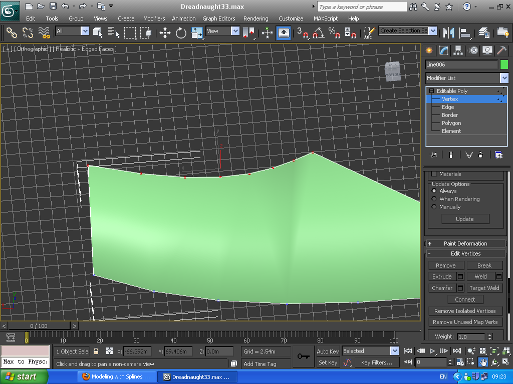
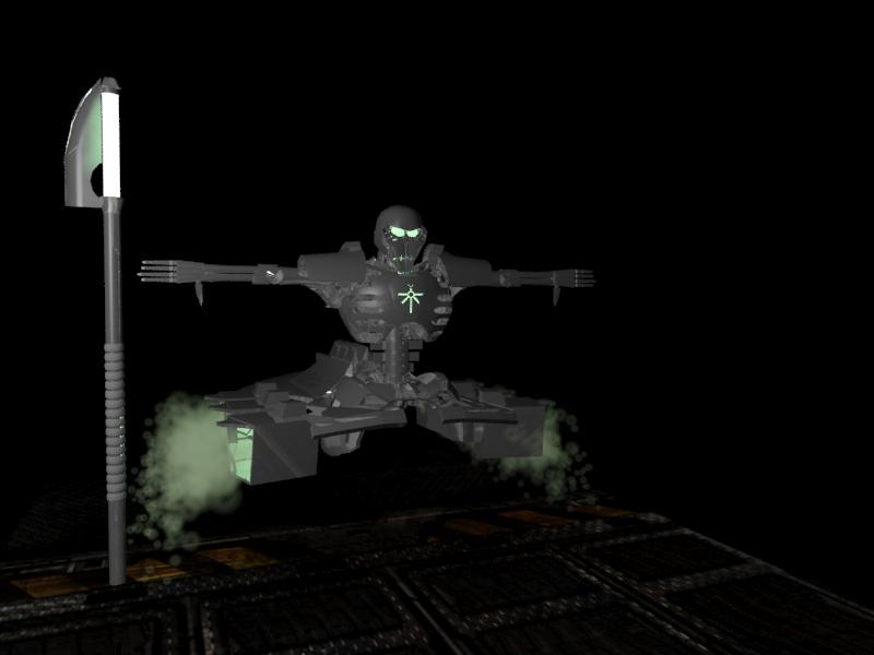
After 6 weeks of learng and work, my 3 models are complete.
My 3 models are:
The Dreadnaught
The Necron Lord
The Necron Destroyer
The last two have their two textures applied. Crome and glowing green. The Dreadnaught still needs some textures,
It will be my next step after I catch up with my write ups. Model-wise I still need to build the enviroment.
Wednesday, 26 October 2011
Friday, 14 October 2011
Wednesday, 12 October 2011
Necron body update.
After yesterdays tutorial this is the stage the necron is up to. Tommorow I will tackle the face.
The Necron is unhappy he gave me two thumbs down!
Creating the body of the necron.
To create the thrusters I made a box into a poly, scaled one side smaller, then in polygon mode the outer side was outlined and then extracted inwards. The lip was made with a 2d shape, then shell,then united to the box, and the top part a united modified box.
The major middle spine was a cylinder streached. I extruded one side then move some polygons in the top. Then I selected polygons in the right and left siee and extruded again.
Finaly I moved cloned with 2 steps.
For the hip I created a circle and attacked it with multiple boolean substrations (box,sphere and capsule were used.)Then I modified it with shell.
Then the lower spine was made and edited with gaps and extrusions, then cloned in 4 steps and rotated, I moved and rotated to get them in shape so the first one entering the hip and the fourth one exiting have a 90 degree diference. Then to join them I used multiple hoses ,and atached them to the disks.
I then created 4 smaller vertions of the spine that conects the hip to the torso. I used one hose for them selecting the highest and lowest spine.
Finaly the torso was made with a champher box, I scaled in the front and back. added a small amount of the sperise modifier and then converted to poly pulling the waiste from left and right inwards and finaly selecting the center polygons I raised moved the top front (chest) slightly outwards.
The major middle spine was a cylinder streached. I extruded one side then move some polygons in the top. Then I selected polygons in the right and left siee and extruded again.
Finaly I moved cloned with 2 steps.
For the hip I created a circle and attacked it with multiple boolean substrations (box,sphere and capsule were used.)Then I modified it with shell.
Then the lower spine was made and edited with gaps and extrusions, then cloned in 4 steps and rotated, I moved and rotated to get them in shape so the first one entering the hip and the fourth one exiting have a 90 degree diference. Then to join them I used multiple hoses ,and atached them to the disks.
I then created 4 smaller vertions of the spine that conects the hip to the torso. I used one hose for them selecting the highest and lowest spine.
Finaly the torso was made with a champher box, I scaled in the front and back. added a small amount of the sperise modifier and then converted to poly pulling the waiste from left and right inwards and finaly selecting the center polygons I raised moved the top front (chest) slightly outwards.
I then used Boolean to cut sections
I also added air vents again by cutting cylinders in the torso.
Major Update 3- techniques I have learned.
Adding blueprints to assist your modeling.
I tryied the technique showed in the lecture creating 3 planes and alinging them and giving them textures.
I must say even though I have seen it used in u tube also I did not like it. You have to set the dimentions of you plains acordingly, then import the material then add the texture then apply it make it 2 sided etc.
I already used vieport pane and found it much easier and secure. Right click on the wireframe or whatever mode you are in. Select the set viewport. Import the image set as bitmap and set it unlocked. for the next two I do the same but keep it locked with zoom. I then create a box accurate in the blue print in view 1. I then zoom the other viewports until the box fits their dimentions then i go back to set vieport and untick the lock.
Creating the base of the necron destroyer- Bevel Profile.
To create the base of the necron destroyer I drew the base of it in 2d on top view. then on front view I creatied a line indicating the curve of the necro body. Then i selected the modifier bevel profile and selected the line as my guide. after some twicking with my guide line the object below was created
Then with boolean I cut out 2 boxes and a cylinder from my shape.
I then duplicated the shape moved the clone below it and substracted it leaving only a shell.
I then converted to poly and deleted half the body to focus on one side. I then selected some polygons on the edge moved and extracted them to get the raised part.
Then I created a capsule and rotated it, moved it and cloned it with 5 steps and then cut them out of the body with boolean to create the air vents in the body.
Major Update 2- techniques I have learned.
Creating the shoulder.
Because the shoulder has a curve I design it in 2d with line.
I then go back to left view and extrude the 2d shape into 3d, Then i plase a box next to it and cut it with boolean. to get the desired shape. Then I add some more boxes and I substract them from the shoulder.
Pivot point
I also had a play around with pivot points. It seems when you group, attach or unite with boolean 2 shapes the pivot point goes somewhere between them. This is not always the desireble effect. In the image bellow I have grouped a cylinder (that rotates which raises or lowers the arm from the shoulder) with 3 cylinders which act as hydralics. I was not sure the angle I wanted the hydralics so I aligned the hydralics to the bottom of the rotatying cylinder. When I grouped and tried to rotate the hydralics did not spin around the cylinder.
So I went to the hierarchy and selected pivot only and then selected to aling to the cylinder, then unselect pivot only. Now the whole mechanism spins around the cylinder.
I do not know if it is needed but I also changed the pivot point for the claws setting it to the base of the claw, so now it i rotate the claw i gices the impresion of opening and closing.
Because the shoulder has a curve I design it in 2d with line.
Then in front view I move the two top vertexes, then with bezier corner I give them a curve.

Pivot point
I also had a play around with pivot points. It seems when you group, attach or unite with boolean 2 shapes the pivot point goes somewhere between them. This is not always the desireble effect. In the image bellow I have grouped a cylinder (that rotates which raises or lowers the arm from the shoulder) with 3 cylinders which act as hydralics. I was not sure the angle I wanted the hydralics so I aligned the hydralics to the bottom of the rotatying cylinder. When I grouped and tried to rotate the hydralics did not spin around the cylinder.
So I went to the hierarchy and selected pivot only and then selected to aling to the cylinder, then unselect pivot only. Now the whole mechanism spins around the cylinder.
I do not know if it is needed but I also changed the pivot point for the claws setting it to the base of the claw, so now it i rotate the claw i gices the impresion of opening and closing.
Major Update 1- techniques I have learned.
Last proper updade was 12 days ago, below I will demonstrate some of the techniques i have learned since then while creating the dreadnought and the Necron destroyer.
Improving "create polygon"
In the picture below you can see a box scaled to one side ad the cut with boolean with a cylinder, this shape will be one of the pieces of the "toe" of the dread.
After the boolean it had no back side. So I when to polygon selected "create" and selected the vertexes.
The result was a weird shape.
I took 2 steps which majorly improved the created polygon.
1. I increaced the number of vertexes. I also activated snap with is set to snap at edges.
2. When creating the polygon I set the snap to vertex so I could acuratly select precisly between many vertexes.
The result below is much better now.
When the "toe" was ready I cloned it and aligned it to the base.
Editing normals.
While creating your object I found it is always good practice to do a fast render just to make sure everything looks alright. The foot I created looks fine.
But when rendered some of the polygons are missing.
Luckly a couple of bosts before I faced the same problem which waws cause because of the normals.
I Deleted 3 of the toes selected the polygons that were darker and modified them them with "normals" and fliping their normals. When I was sure of the result I replicated the tow again.
2d shape manypulation, bezial corners and Welding vertexes.
At this point I am creating the claw of the dreadnought. To create the clade like claw I selected "line" in the 2d shapes. I did a tetragon with straight lines. Then I moved into the editor and chose the vertex selection.
I selected one of the vertexes, that touches the edge that I want to curve, and right click and select bezial type of corner.
Now two controlers appear, one for modifing each edge connected to the vertex. I do this twice and move around the vertexes and end up with the result bellow.
When I am happy with the shape I turn it into a 3d object with shell.
I set the values of the inner amount. then i cinvert to editable poly and select the top edges and place them in the center to create the sharp edge.
I repeat for the other side
Now the shape is made but it is not closed and I have vertexes overlaping each other.One way is to select weld and drag and drop but with target weld it can be done much faster.
WWhat target weld does is it allows you to weld groups of vertexes that are within a desired value. I selected all the top vertexes and selected in the target weld window, a control window appearswere you can alter the welding distance in real time before confirming. It will also remember you last selected value.
In the picture below the value is so high that not only is it welding the points on top of eash othe but neighbour vertexes also, so I lower the value.
It also lets you now how many vertexes were selected and how many there are after welding.
Even so bellow was a confirmation of welding.
Improving "create polygon"
In the picture below you can see a box scaled to one side ad the cut with boolean with a cylinder, this shape will be one of the pieces of the "toe" of the dread.
After the boolean it had no back side. So I when to polygon selected "create" and selected the vertexes.
The result was a weird shape.
I took 2 steps which majorly improved the created polygon.
1. I increaced the number of vertexes. I also activated snap with is set to snap at edges.
2. When creating the polygon I set the snap to vertex so I could acuratly select precisly between many vertexes.
The result below is much better now.
When the "toe" was ready I cloned it and aligned it to the base.
Editing normals.
While creating your object I found it is always good practice to do a fast render just to make sure everything looks alright. The foot I created looks fine.
But when rendered some of the polygons are missing.
Luckly a couple of bosts before I faced the same problem which waws cause because of the normals.
I Deleted 3 of the toes selected the polygons that were darker and modified them them with "normals" and fliping their normals. When I was sure of the result I replicated the tow again.
2d shape manypulation, bezial corners and Welding vertexes.
At this point I am creating the claw of the dreadnought. To create the clade like claw I selected "line" in the 2d shapes. I did a tetragon with straight lines. Then I moved into the editor and chose the vertex selection.
I selected one of the vertexes, that touches the edge that I want to curve, and right click and select bezial type of corner.
Now two controlers appear, one for modifing each edge connected to the vertex. I do this twice and move around the vertexes and end up with the result bellow.
When I am happy with the shape I turn it into a 3d object with shell.
I set the values of the inner amount. then i cinvert to editable poly and select the top edges and place them in the center to create the sharp edge.
I repeat for the other side
Now the shape is made but it is not closed and I have vertexes overlaping each other.One way is to select weld and drag and drop but with target weld it can be done much faster.
WWhat target weld does is it allows you to weld groups of vertexes that are within a desired value. I selected all the top vertexes and selected in the target weld window, a control window appearswere you can alter the welding distance in real time before confirming. It will also remember you last selected value.
In the picture below the value is so high that not only is it welding the points on top of eash othe but neighbour vertexes also, so I lower the value.
It also lets you now how many vertexes were selected and how many there are after welding.
Even so bellow was a confirmation of welding.
Subscribe to:
Posts (Atom)